Remco van Dasselaar (April 2018 – February 2019)
Link to report in the repository: https://essay.utwente.nl/77349/1/Dasselaar_MA_ET.pdf
SUMMARY
Wind turbines are designed to survive at least twenty years of service life. In practice, many components fail before these twenty years. Current used failure prediction methods do not consider the loads acting on the system. In order to reduce the operations and maintenance costs, there is a need for a lifetime prediction method based on the actual loads on the system. (Figure 1)
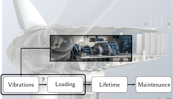
Figure 1: Research wind turbine drive train load assessment.
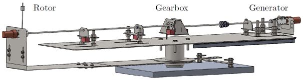
Figure 2: CAD overview of the test bench.
This research is a feasibility study to the use of a structural model to predict the loads (forces and torques) based on acceleration vibrations. This is done using a test bench (Figure 2). Three different structural models are investigated based on an analytical approach, using SPACAR and a manually defined FEM model. The manually defined FEM model appeared the most suitable and is validated by the resonance frequencies and amplitudes. The resonance frequencies of the test bench and the FEM model correspond. The amplitude is checked for the exciting rotor force. This showed unreliable results with prediction errors of about 50%. This can be due to the use of an inverse matrix in the FEM model, which is sensitive to small changes in geometry and stiffness. Also, the test bench has some uncertain parameters, for example, the spring located under the gearbox. The bearing force prediction for different rotor speeds shows the expected dynamic behavior with significant peaks at resonance frequencies.
KEY RESULTS
- A simple defined structural FEM model describing the testbench bending in the z-direction and shaft torsion with relevant details like the gearbox ratio. (Figure 3)
- Corresponding resonance frequencies of the test bench and structural model. (Figure 5)
- Validation by the rotor force prediction showed errors of about 50% (Figure 4 and 5)
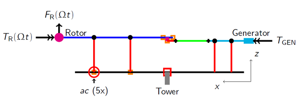
Figure 3: Structural FEM model.
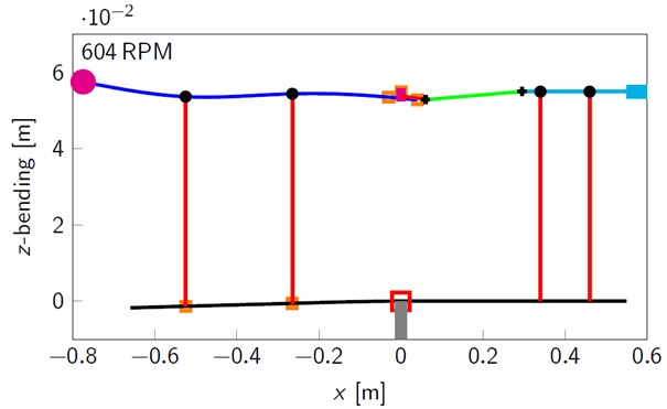
Figure 4: Motion prediction at 604 RPM.
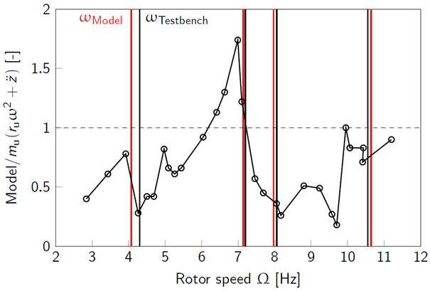
Figure 5: Rotor force validation at different rotor speeds.