Rick van der Gouw – Apollo Global R&D (September 2016 – November 2017)

Summary
The thesis studies the feasibility of a Tyre Monitoring System (TMS) within a tyre. The goal is to find and validate features based on strain measurements at the Inner Liner (IL) that describe tyre road interaction. With the application of a TMS the behaviour between the tyre and road is monitored directly, which can be used to implement in safety systems of the vehicle. Two key parameters are selected to identify which describe the first steps of the interaction. These are the contact area and the point of slip within the contact area. Experiments in quasi-static conditions are performed to validate these features. By using a TMS within the tyre, as shown in Figure 1, the strain during a rotation is measured. This strain data contains data to identify the start and end of the contact and the point of slip.
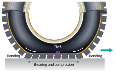
Figure 1 TMS placement within the tyre
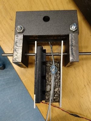
Figure 2 Tensile test setup
With this length as input, an estimation for the contact area is made. Furthermore a strain drop can be recognised for the moment of slip of a tread block. From quasi-static experiments the following key features are concluded:
· The contact length can be identified by the strain rate but with a consistent error of 15%
· The contact area is estimated by using a curvature estimation based on the contour of the tyre (See Figure 3, magenta line)
· The tensile tester test-setup is suitable to simulate the slip behaviour (Figure 2)
· The transition from stick to slip phase is recognised by a strain drop (Figure 4)
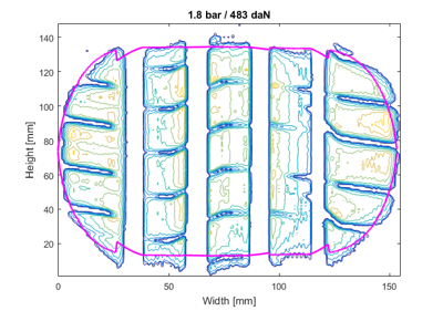
Figure 3 Footprint estimation

Figure 4 Strain drop
System implementation
With the estimation of the footprint and slip feature proven for quasi-static conditions experiments can be extended to obtain this data in dynamic situations. The end goal is to obtain a real time estimation of the effective contact area and the part of the area which is in slip. A visualisation of this estimation is shown in Figure 5.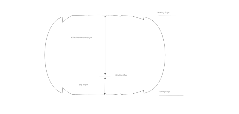
Figure 5 Footprint estimation