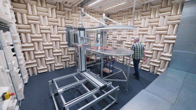
The AeroAcoustic wind tunnel is one of the main test facilities of the Engineering Fluid Dynamics (EFD) Group of the UT. It is also known as the 'silent' wind-tunnel because its walls have a special treatment meant to absorb practically all the noise produced by the air flow, which can reach up to 240 km/h. Thanks to that, the tunnel is suited for measuring simultaneously the aerodynamic and the noise of applications. The 0.7 x 0.9 m2 test section has a Reynolds number of 324.000 based on the criteria of 0.1√S. We can use this test facility with airfoil models with a chord of roughly 0.3 m, reaching a chord-based Reynolds number of up to 1.2 million.
Description of the Wind Tunnel circuit
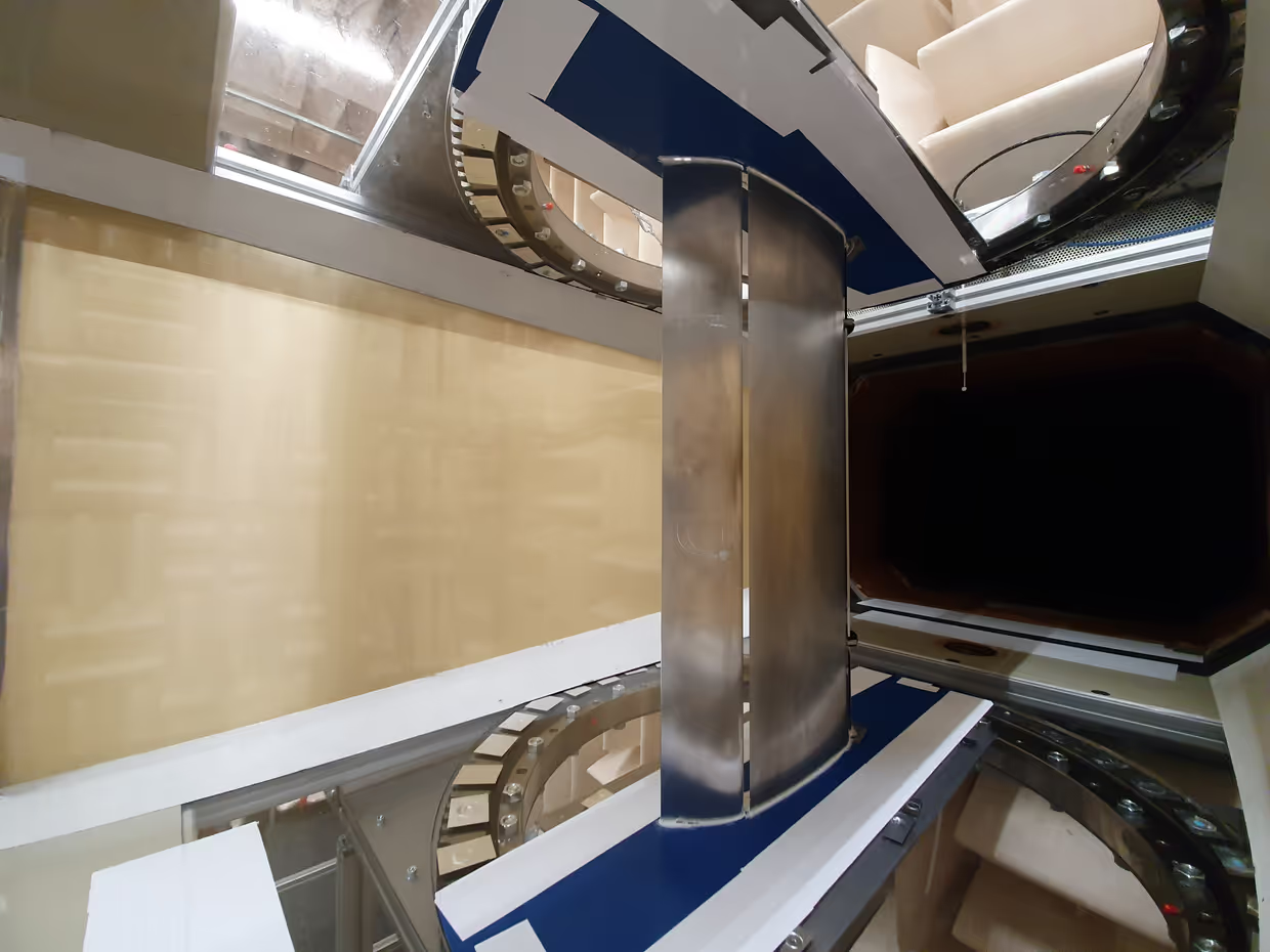
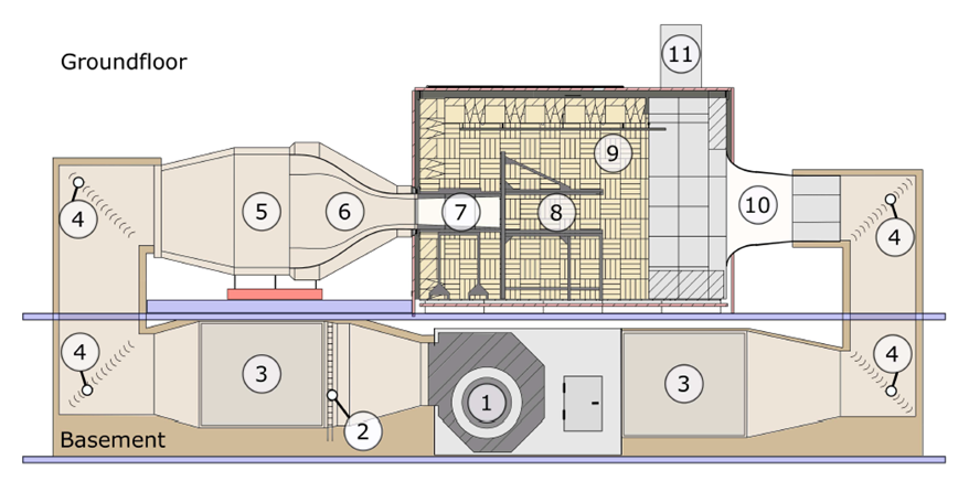
A schematic layout of the silent Wind Tunnel at the University of Twente is shown above. A 130 kW electrical motor connected to two large radial turbines powers the system (1). Due to the heat created by friction at high velocities, the air is cooled by a water-cooled heat exchanger (2). To avoid propagation of the noise generated by the turbines and tubes of the heat exchanger to the anechoic chamber, acoustic dampening panels are installed (3). Upstream of the test section, the flow is made laminar when it passes through the settling chamber (5) and a number of anti-turbulence grids. Subsequently, the air flows through a contraction (6) and reaches a closed test section (7) and exit the nozzle into the anechoic chamber (9). The jet stream is recollected at (10) and a closed system is formed. Additional acoustic damping is applied downstream of the collector in order to reduce reflections and noise generated by the corner vanes (4).
Anechoic chamber
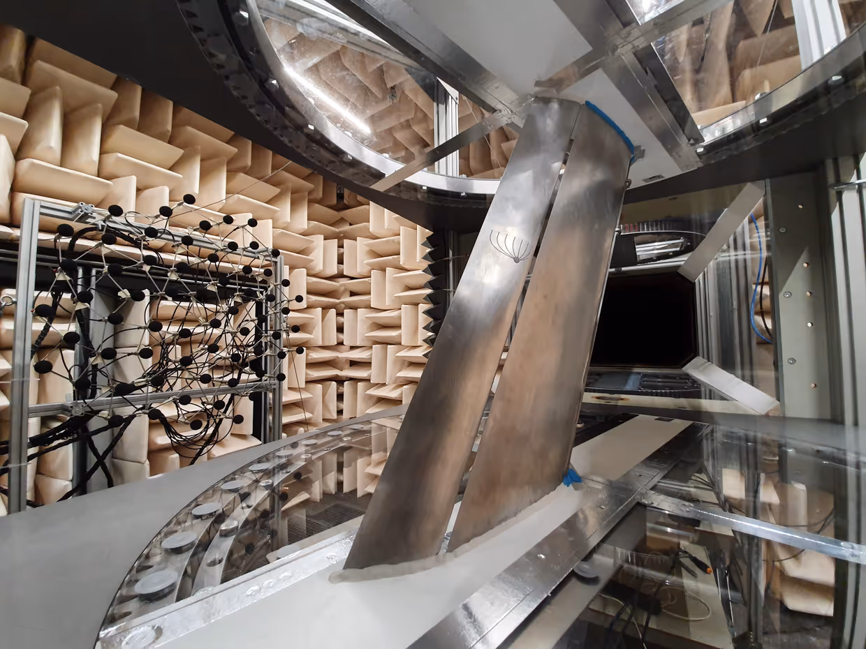
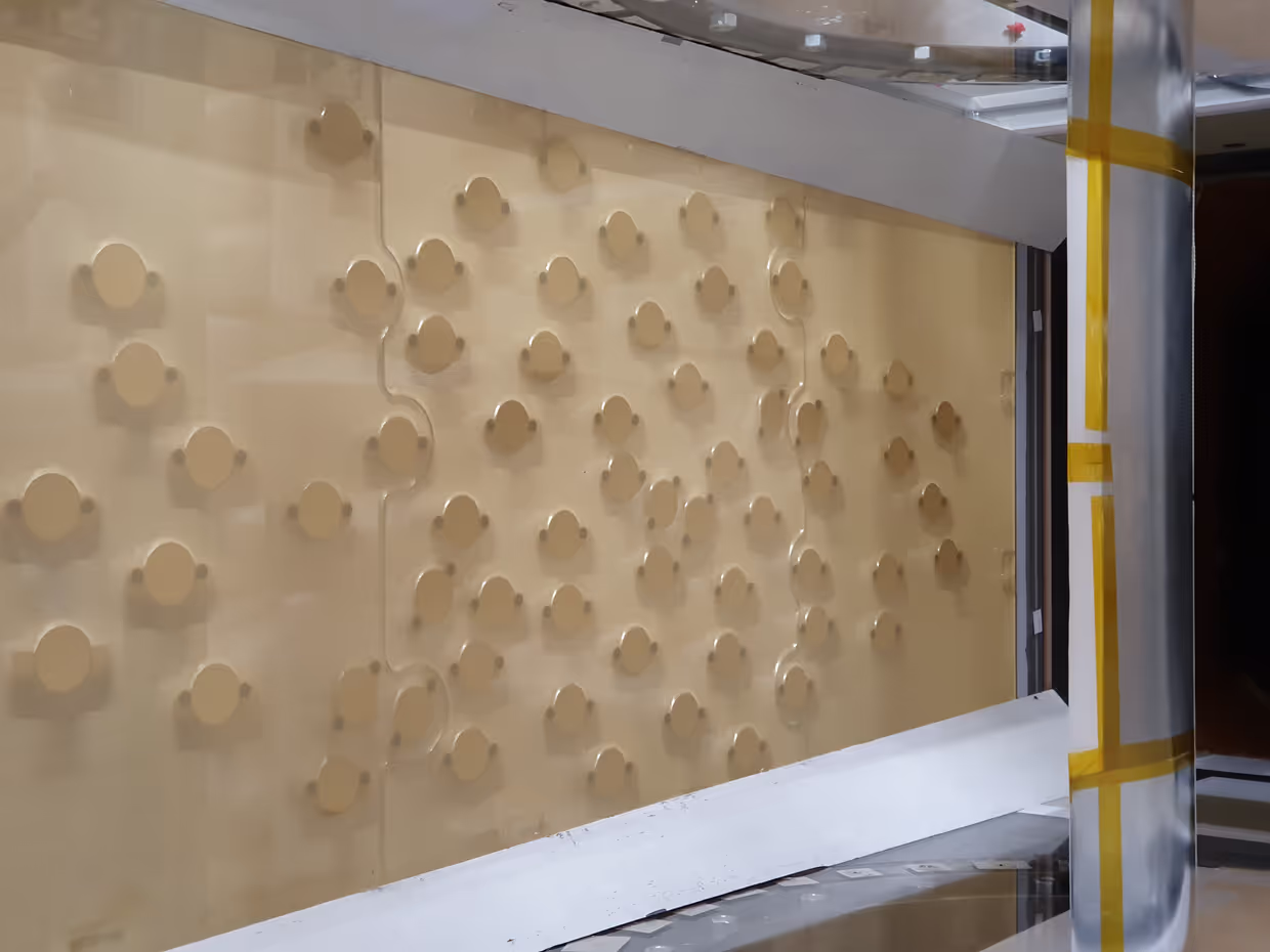
The test section of the wind tunnel is located inside of a large anechoic chamber which has dimensions 6 × 6 × 4 m. In 2018, we refurbished the anechoic chamber in its current form. In the new configuration, wedge type absorbers covering approximately 80% of the anechoic chamber walls replaced the flat absorbers. Thick flat absorbers of 350 mm and 550 mm cover the other 20% of the anechoic chamber. The choice for wedges was made to improve the anechoic chamber capacity to absorb tonal noise components. The flat absorbers are placed in the regions subject to high wind speed where mineral wool wedges could not sufficiently resist the aerodynamic load. The target anechoic chamber cut-off frequency of 160 Hz is obtained through a combination of materials and construction techniques. The design choices considered the optimization of the acoustic performance and constraints related to the site, i.e. maximum occupied area, safety, health and fire hazard. The anechoic chamber walls are lined with the commercial wedges ASONAD-MF composed of mineral wool covered by an acoustically transparent fiberglass cloth with double tips. The anechoic chamber was qualified following the International Standard ISO 3745:2012 Annex A, “General procedures for qualification of anechoic and semi-anechoic rooms”.
Test section configurations