Introduction
In free-flow electrophoresis, analytes are separated continuously in an electrical field applied perpendicular to a thin pressure driven carrier electrolyte flow between two insulating plates. The sample mixture is injected into the carrier electrolyte flow and with increasing residence time the differently charged components split up into diverging lanes which can be collected at various device outlets, as shown in Fig. 1. Since the introduction of free-flow electrophoresis (FFE) in the 1960s, this separation method has found a permanent position among analytical and preparative methods in biochemistry and chemistry for the separation of e.g. cells, organelles, peptides, proteins, inorganic and organic compounds.
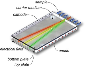
Fig 1. Principle of free-flow electrophoresis
The miniaturization of FFE implies several advantages especially considering sample volume and separation speed. In contrast to the tens of milliliters of sample consumed by conventional large scale FFE devices, microfluidic FFE systems require only tens of nanoliters up to hundreds of microliters of sample. This is especially interesting in clinical analysis where often only low sample volumes are available. Furthermore, instead of residence times of up to tens of minutes, microfluidic FFE (µ-FFE) devices separate within several seconds. The aim of this project is to develop a microfluidic free-flow electrophoresis device (as shown in figure 2 and 3) which eventually might find application in so called proteomics-on-a-chip systems for proteome analysis.
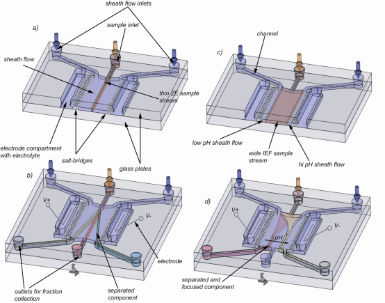
Fig 2. Illustration of the µ-FFE device and applied separation methods: a), b) application of free-flow zone electrophoresis: a) The sample mixture is hydrodynamically focused by two sheath flow streams containing buffer only and no voltage is applied. b) Voltage is applied and different components separate due to their size to charge ratio. c)-d) application of free-flow isoelectric focusing: c) a wide sample mixture and ampholytes are sandwiched between two thin sheath flow streams of high and low pH. d) In the presence of an electrical field the ampholytes build up and buffer a linear pH gradient. Components move towards and focus at their isoelectric points.
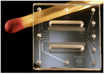
Fig 3. Micro fabricated glass free-flow electrophoresis chip
Literature
Kohlheyer, D., G. A. J. Besselink, et al. (2006). "Free-flow zone electrophoresis and isoelectric focusing using a microfabricated glass device with ion permeable membranes." Lab Chip 6: 374-380.
Kohlheyer, D., J. C. T. Eijkel, et al. (2007). "Microfluidic High Resolution Free-Flow Isoelectric Focusing." Anal. Chem. 79(21): 8190-8198.
Kohlheyer, D., J. C. T. Eijkel, et al. (2008). "Miniaturizing free-flow electrophoresis - A critical review." Electrophoresis, in press.
Funding
This research is funded by the Dutch foundation for technology STW as being part of the national project: “Proteomics on a chip for monitoring autoimmune diseases”