Project Members
Jaap Flokstra (Project Leader)
Johannes Pleikies (PhD student)
Former Members:
Martin Podt (PhD student)
Imdat Yikilmaz (Master student)
Collaborating group:
Gravitational Wave Antenna MiniGRAIL, located in the Kamerlingh Onnes Laboratory, Leiden University, The Netherlands
Funding
The actual work was supported by the dutch technology foundation STW.
Project “Nearly quantum-Limited squids for extreme small displacements sensors: Application to MiniGRAIL” ( TTN.5879)
Introduction

We are developing low-Tc SQUID amplifiers and -systems which can be utilized for high-precision measurements of electrical currents or any quantity that can be transformed into it. Possible fields of application are for example current amplification and detection, displacement sensors for detection of gravitational waves or an utilization in STM- and AFM-systems or the readout of thermal detectors for astronomy (TES, STJ).
dc-SQUID amplifiers
Low-Tc dc-SQUIDs have proven to be able to measure magnetic fields with an unrivaled sensitivity. By integrating a coil on the SQUID, one can transform the magnetometer into an amplifier. The main differences to the conventional SQUID magnetometers are:
1.The integrated coils can influence the performance of such sensors hardly predictable way.
2.The SQUID is also interacting with the connected load and thus, depending on the application, back-action noise and other mutual interaction between amplifier and object of observation have to be taken care of.
Currently we concentrate on using the SQUID as an amplifier with the best possible sensitivity reachable by optimizing design and cooling behavior at sub-kelvin bath temperatures. The designated application, the readout of the resonant mass gravitational wave antenna MiniGRAIL, further asks for special design-criteria important for reading out a load with a high quality-factor: low back-action, good coupling factor and a possible stable operation in flux-locked loop. The designs are fabricated at IPHT Jena/Germany.
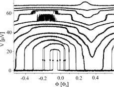
Using numerical simulations on models including parasitic elements introduced by the integrated input coils, we are able to predict the behavior in a good way. The figure below depicts the simulated and the measured Φ-V-characteristics of one of our sensors operating at a temperature of 600mK. Most features in the characteristics can be explained, including a hysteresis originating from resonances in the integrated coils. [1,2]
|
|
(a) simulated characteristic | (b) measured characteristics |
Fig. 1: Φ-V-Characteristics of one of our SQUID designs for different bias currents at a temperature of 100 mK. Hysteretic branches are indicated by arrows. | |

Furthermore, additive noise of the devices can be extracted from the simulations. The picture below shows the temperature-dependent measurement of the sensitivity of one of our designs as well as a comparison to the simulation on the extracted model of the sensor. [1]
|
|
(a) | (b) |
Fig. 2: Sensitivity for one of our SQUID designs. (a) temperature dependence of the additive noise at the best working point. (b) simulated sensitivity around the same working-point at a temperature of 600 mK. | |


Cooling behavior of the sensors
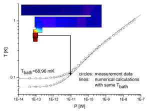
Another important issue under investigation is the thermal behavior of the sensing device. The sensitivity of practical dc-SQUIDs cooled down to temperatures below 1 K is often limited by the hot-electron effect. So-called cooling fins, electrically negligible extensions of the volume of the resistor, can be attached to weaken this effect. We characterized different configurations of resistors with cooling fins by dissipating power and measuring the Johnson noise to determine the effective electron temperature, which directly influences the sensitivity of our sensors. We could reproduce our measurement data by performing FEM calculations based on the theory of the hot electron effect and the thermal transport via the electrons within the geometry of resistor and cooling fin. This turns out to be a powerful tool to predict and optimize the minimum reachable temperature and thus the optimum reachable sensitivity.
| Fig. 3: Measured and calculated characteristics for one of the investigated test-structures. In measurement and simulation, power P was dissipated in the resistor, and the resulting electron temperature T in the same area was determined. The inset shows a FEM-calulation at one particular bath temperature and dissipated power. The color scale represents the electron temperature T. The indicated area is the resistor. The upper, U-shaped, blue, and thus colder, part of the geometry is the cooling fin. |
2nd generation SQUIDs
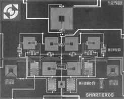
Besides conventional dc-SQUIDs, our group also works on so-called 2nd generation SQUIDs, based on the (Double-) Relaxation Oscillation SQUID, (D-)ROS, device family. Those sensors can for example be used as magnetometers or current amplifiers, to match low noise signal sources to the readout via room temperature electronics [4] or for replacing the usual flux-locked loop using an on-chip feedback technique [3].
|
|
(a) | (b) |
Fig. 4: Chip-pictures of (a) a DROS and (b) a Smart-DROS, a chip with on-chip feedback | |

References
[1]“Numerical studies on dc-SQUID sensors with tightly coupled input coil”, J. Pleikies, O. Usenko, and J. Flokstra, Journal of Physics Conference Series, 97, 012254 (2008)
[2]“SQUID Developments for the Gravitational Wave Antenna MiniGRAIL”, J. Pleikies, O. Usenko, K. H. Kuit, J. Flokstra, A. de Waard, and G. Frossati, IEEE Trans. on Appl. Supercond., 17, 764 (2007)
[3]“An experimental double relaxation oscillation superconducting quantum interference device with on-chip feedback”, M. Podt, J. Flokstra, and H. Rogalla, Superconductor Science and Technology, 17, 701 (2004)
[4]“Two-stage amplifier based on a double relaxation oscillation superconducting quantum interference device”, M. Podt, M. J. van Duuren, A. W. Hamster, J. Flokstra, and H. Rogalla, Appl. Phys. Lett., 75, 2316 (1999)