TERMINATIONS OF SUPERCONDUCTING COILS IN THE ITER AND JT-60SA FUSION REACTORS NEED TO BE STABLE BALANCED IN TERMS OF AC LOSS, DC RESISTANCE AND CURRENT DISTRIBUTION
Research financially supported by the ITER Organisation, the Institute of Plasma Physics Chinese Academy of Sciences, Hefei, Peoples Republic of China, and in collaboration with the National Institute for Fusion Science, Toki, Japan (JT-60SA).![]()

![]()
![]()
Joints are the connections between superconducting coil terminations and current feeders. The objective of this research is to analyse the electro-magnetic and thermal behaviour of joints in different plasma operating scenarios. Since specific design properties of the joints are to be analysed, the simulation tool is required to have a high level of detail. The model, called JackPot - an abbreviation of Jacket-Potential, is able to calculate the trajectories of all strands in a CICC, and it uses this as a basis to calculate all electrical properties of the cable and its interaction with the joint normal conducting components.
JackPot-AC calculates the strand current distribution and power dissipation that are used in post-processing routines which calculate the temperature evolution and magnetic field on each strand element. After that, the temperatures and fields are used to calculate the critical current in each strand element at each time-instance, which are used for estimating the stability margin of the joint.
Joints stability
The twin-box lap type joint is a type of joint with proven reliability and suitable assembly used for the ITER coils. However, measurements on sub-sized and full-sized joints for coils have also shown signs of thermal instability as flux jumps in pick up coil measurements when subjected to operating conditions similar to ITER scenarios. These operating conditions involve transient fields within the intended operating range of the coil. Due to the transient background field, coupling currents in the strands repeatedly initiated local quenches. Understanding this quench behaviour may contribute in predicting the stability of the whole coil.
Joint modeling
The model, called JackPot - an abbreviation of Jacket-Potential, is able to calculate the trajectories of all strands in a CICC, and it uses this as a basis to calculate all electrical properties of the cable together with the normal conducting components of the joint. The thermal model allows the calculation of the helium, cable and copper sole temperature along their main axis. For a higher level of detail, the temperature is calculated for each individual petal.
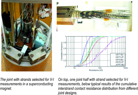
Joint measurements
The interstrand and strand to copper sole contact resistance distribution must be measured to obtain accurate input data for the modeling of current distribution and DC current joint resistance. The AC loss is required to evaluate the correctness of the prediction for AC power loss generation and associated temperature increase.
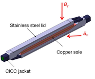
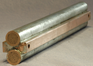
Left the design of the ITER CC joint and right a prototype joint on top of the calorimeter for AC loss measurement.
Validation of the joint model
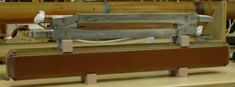
Below the assembly of a mock-up joint is shown. The AC loss measurement was carried out in a homogeneous applied AC field with an amplitude of 0.2 T and a frequency ranging from 0.01 to 0.16 Hz. The plot right below shows the results for both transverse field orientations (parallel and perpendicular to the broad side of the copper plate in the middle).
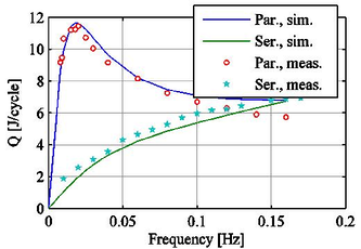
The mock-up joint assembly, measured and simulated AC loss of the joint versus frequency, under different angles of the applied AC field.
Predictions of joint model
The first plot below shows the total power dissipation in PF joints during an ITER plasma scenario. A clear peak occurs right after the start, where the dI/dt and dB/dt components are particularly large, to initiate the plasma. In this phase, all joints dissipate approximately the same power. However, during the ramp-up and ramp-down phases, the top and bottom joint dissipates considerably more power, whereas during the burn phase, their dissipation is almost the same. Considering that all joints carry the same transport current, which is highest during the burn phase, the higher power dissipation in the top and bottom joints can only be caused by their larger radial component of the changing background field. The differences in their coupling currents are quite clear, as can be seen below.
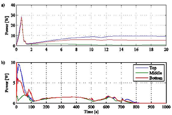
Total power dissipation in three ITER PF2 joints, (a) during the plasma discharge phase and (b) during the whole ITER 15 MA scenario.
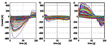
Strand currents in the centre of the upper cable in (a) the PF2 top joint, (b) the PF2 middle joint and (c) the PF2 bottom joint.
For more information, please contact Arend Nijhuis: ![]()
![]()
Links: ITER
Papers on this subject
- E.P.A. van Lanen, A. Nijhuis, ‘JackPot: A novel model to study the influence of current non-uniformity and cabling patterns in cable-in-conduit conductors’, Cryogenics 50 (2010) 139–48E.P.A. van Lanen, J. van Nugteren and A. Nijhuis ‘Full-scale calculation of the coupling losses in ITER size cable-in-conduit conductors’, Supercond. Sci. Technol. 25 (2012) 025012 (8pp)
- E.P.A van Lanen, W. Offringa and A. Nijhuis ‘Validation of a strand-level CICC-joint coupling loss model’, Supercond. Sci. Technol. 25 (2012) 025013 (8pp)
- E.P.A. van Lanen and A. Nijhuis, “Numerical analysis of the DC performance of ITER TF samples with different cabling pattern based on resistance measurements on terminations”, 2011 Supercond Sci Technol 24 (8) 085010
- Van Lanen, E.P.A., Nijhuis, A.”Simulation of interstrand coupling loss in cable-in-conduit conductors with JackPot-AC”. IEEE Trans App Supercond 21 (2011), art. no. 5624609, pp. 1926-1929