DEVELOPMENT OF MECHANICAL-ELECTROMAGNETIC CABLE MODELS FOR QUANTITATIVE PREDICTION OF STRAIN, CURRENT AND POTENTIAL DISTRIBUTION WITH THE AIM OF CONDUCTOR IMPROVEMENT.
Research financially supported by the ITER Organisation. 
Testing model coils or short samples of large current – high magnet field composite conductors often leads to results which are difficult to understand. The challenging and complex interaction of all involved phenomena, e.g., lattice strain and damage, material diffusion processes, magnet field, current sharing, potential distribution and thermal instability, requires dedicated scientific research and very detailed modeling of cabled superconducting composites. Below we give a brief impression of the capabilities of our TEMLOP and JackPot-AC models. The scientific results of this work leads not only to a notable improvement of superconductors (our TEMLOP model caused the breakthrough for the ITER TF conductor issues in 2006) but also to drastic improvement of the testing method used for, among others, qualification of ITER conductors.
ITER conductors and performance
The impressive and unprecedented ITER Magnet System comprises various huge superconducting coils that magnetically confine, shape and control the plasma. The power of the magnetic fields required to confine the plasma in the ITER Vacuum Vessel is extreme. The superconducting magnets are designed to achieve operation at high magnetic field (13 Tesla) and huge current (up to about 70,000 A). The coils will be made of Cable-In-Conduit superconductors (CICC), in which a bundle of superconducting Nb3Sn strands (>1000) is cabled together and cooled by flowing Helium, and contained in a structural steel jacket (see photo below). A heat treatment is needed to react the material and form the brittle and strain sensitive Nb3Sn superconductor.
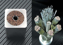
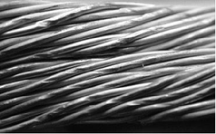
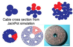
A full ITER superconductor from the Toroidal Field Magnets with 900 superconducting strands and 510 copper strands of 0.8 mm diameter (left & middle) and the twisted structure of the cable elements with many strand crossings (right).
The open nature of the cable bundles in the sizeable CICCs for ITER, creating a void fraction of around 30 % to be filled with helium, is needed for sufficient cooling capacity preserving stable behaviour. When subjected to the enormous electromagnetic forces after charging of the coils, the open nature of the cable gives scope for significant cable compression and associated strand deflection through periodic bending and contact stress. This lead to a significant degradation of the cables when tested under magnet operating conditions and was a serious threat for ITER. Dedicated cable models, treating all the involved phenomena down to the strand level, are required to understand the basic mechanisms and provide a solution.
TEMLOP cable electromagnetic-mechanical model
We developed a model that is capable in optimising the design of complex cabled superconductors for electromagnetic transverse load (TEMLOP-Model). The first results of computations on an ITER type conductor immediately lead to striking new insights, based on the detailed charaterisation of mechanical and electromagnetic properties of ITER type Nb3Sn strand in the Pacman and TARSIS facilities and cable research with the Cable Press at the University of Twente.
The most important a priori prediction and conclusion of this work in 2006 was that the problem of the severe degradation of large CICCs, the way they were designed for ITER at that time, could be solved by increasing the cabling pitches. The principle is based on a more homogeneous distribution of the stresses and strains in the cable and significantly moderate the local peak stresses associated with intermediate twist pitches.
The model gives a good description for the mechanical response of the strands to a transverse load, from layer to layer in the cable, based on the strand stiffness and cable void fraction (see schematic principle below). The transport properties of the strand, extensively characterised in the Pacman and TARSIS facilities, depend on their position in the cable and are fully taken into account, which allows accurate predictions.
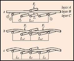
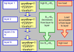
Principle of the TEMLOP model with left the scheme of strand interaction from strand layer to layer and right the mechanical and electromagnetic conditions through the entire cable.
TF conductor optimisation
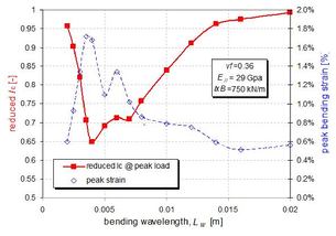
Thanks to the research at the University of Twente on strand and cable electromagnetic-mechanical properties and the development of the TEMLOP model, we discovered the influence of the characteristic bending wavelength and were able to make an a priori prediction that appeared essential for improvement of the cables for the Toroidal Field (TF) coils. The illustration below left shows the dependency between the peak strain, the reduction in performance (Ic/Ic0) and the characteristic bending wavelength (Lw).
The prediction was validated with a test one year later. A cable manufactured with the ‘Twente TF design’ (indicated with OST2) was tested together with the ITER reference cable pattern (OST1) and the results are shown below right. The outstanding test result confirmed that the OST2 with predicted Twente enhancement gives an crucial improvement of the current sharing temperature (Tcs) up to 7.4 K, no degradation with cycling and a very high temperature margin for an operating temperature of less than 5 K.
2006: TEMLOP prediction, no experimental data available at that time to prove the prediction that longer twist pitch enhances lateral strand support and reduces transverse load degradation.
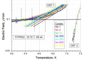
2007: validation, OST2 performance in good agreement with a priori TEMLOP prediction from no loading effect, no cyclic degradation, no “warm up cool down” effect observed (plot CRPP, Villigen).
CS conductor optimisation
The first tests of the conductors for the Central Solenoid (CS) at the end of 2010 revealed a large degradation when tested under cyclic magnet operating conditions. The cable is supposed to withstand 60,000 current pulses without trouble. But tests at the SULTAN facility (), Switzerland, showed serious degradation in short samples of cable after about 10,000 pulses.
The solution used for the TF conductors could not be implemented straightforward to the CS conductors. The reason is that the CS coils are subjected to alternating current and magnet field causing AC power loss, to a much larger extent than the TF coils. AC loss results into higher temperature of the conductor and must therefore remain restricted to a tolerable level in order to guarantee stable operation. A detailed electromagnetic cable model was required to study the actual relation between cable structure and AC loss.
For this reason we developed the JackPot-AC model (JackPot stands for Jacket Potential) that takes into account the detailed trajectories of all strands in the cable, their contacts, electromagnetic properties, self-field and applied magnet field. The cable structure and the electrical network circuit with interstrand contact resistances and inductances is shown below.
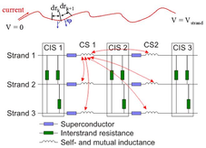
The stepwise build cable structure of a cable taking into account all strand trajectories and cable compaction (left) and the electrical network circuit with interstrand contact resistances and inductances (right).
A typical result is depicted in the plot below (left). The Jackpot-AC model revealed for the first time that an increase of the lower stage twist pitch can lead to a lower overall AC loss. With JackPot-AC, an extensive parametric study is performed with twist pitch variation of all cable stages. An important result is presented in the plot below (right) where the so-called twist pitch ratio “β” in the cabling sequence from one cable stage to the next: Lp2= b*Lp1, Lp3=β*Lp2 etc, β is varied from 1.05 to 1.50 and the first stage twist pitch Lp1 is taken 100 mm. The lowest AC loss is reached for a ratio β close to 1. The combination of the TEMLOP and JackPot-AC predictions lead to an optimized cable pattern for the CS conductor (CS-Twente) with Lp1=110 mm and β=1.1.
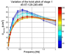
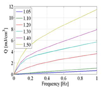
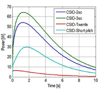
The increase of the AC loss versus frequency of the applied alternating magnet field for variation of the first stage twist pitch (left) and the influence of the twist pitch ratio “β” in the cabling sequence (middle) and the power loss generation of four types of cable designs proposed by ITER IO and the CS-Twente predicted by JackPot-AC.
The CS-Twente proposal was approved on the Sultan Working Group Meeting in June in Switzerland and the cable was manufactured at Tratos Cavi in Italy in August 2011. The test is at the Sultan facility in Switzerland in March 2012. Below the conductor options are compared after manufacture. Shown is the last sub stage of the full-size cable, composed of six such elements with a central cooling channel in the center.
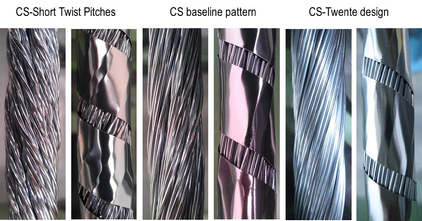
The ITER IO type of cables and the CS-Twente type after manufacture, the final cable is composed of six such elements.
For more information, please contact Arend Nijhuis: ![]()
![]()
Links: ITER
Papers on this subject
- A. Nijhuis, E.P.A. van Lanen and G. Rolando, ‘Optimisation of ITER Nb3Sn CICCs for coupling loss, transverse electromagnetic load and axial thermal contraction’, 2012 Supercond. Sci. Technol. 25 015007
- A. Nijhuis and Y. Ilyin, ‘Transverse Load Optimisation in Nb3Sn CICC Design; Influence of Cabling, Void Fraction and Strand Stiffness’, Supercond. Sci. Technol. 19 (2006) 945-962. IOP Select article
- E.P.A. van Lanen, A. Nijhuis, ‘JackPot: A novel model to study the influence of current non-uniformity and cabling patterns in cable-in-conduit conductors’, Cryogenics 50 (2010) 139–48E.P.A. van Lanen, J. van Nugteren and A. Nijhuis ‘Full-scale calculation of the coupling losses in ITER size cable-in-conduit conductors’, Supercond. Sci. Technol. 25 (2012) 025012 (8pp)
- E.P.A van Lanen, W. Offringa and A. Nijhuis ‘Validation of a strand-level CICC-joint coupling loss model’, Supercond. Sci. Technol. 25 (2012) 025013 (8pp)
- Qin, J., Wu, Y., Warnet, L.L., Nijhuis, A., A novel numerical mechanical model for the stress-strain distribution in superconducting cable-in-conduit conductors”. Supercond Sci Technol 24 (6) (2011) art. no. 065012
- A. Nijhuis, H.H.J. ten Kate, and P. Bruzzone, ‘The Influence of Lorentz Force on the AC Loss in Sub-size Cable-In-Conduit Conductors for ITER’, IEEE Transactions on Applied Superconductivity, Vol. 7, No. 2, June 1997, 262-265
- A. Nijhuis, N.H.W. Noordman, O.A. Shevchenko, H.H.J. ten Kate, and N. Mitchell, ‘Electromagnetic and Mechanical Characterisation of ITER CS-MC Conductors Affected by Transverse Cyclic Loading, Part 3: Mechanical Properties,’ IEEE Transactions on Superconductivity, Vol. 9, no.: 2, June 1999, pp. 165-168
- A. Nijhuis, Y. Ilyin, W. Abbas, B. ten Haken and H.H.J. ten Kate ‘Performance of an ITER CS1 Model Coil Conductor under Transverse Cyclic Loading up to 40,000 cycles’, IEEE Trans. Appl. Supercond., Vol. 14, No. 2, (2004), pp. 1489-1494
- A. Nijhuis, Y.A. Ilyin, W. Abbas, H.H.J. ten Kate, M.V. Ricci and A. della Corte, ‘Impact of void fraction on mechanical properties and the evolution of coupling loss in ITER Nb3Sn conductors under cyclic transverse loading’, IEEE Trans. Appl. Supercond. Vol 15, No. 2, June 2005, 1633-1636
- A. Nijhuis, Y. Ilyin, ‘Transverse cable stiffness and mechanical losses associated with load cycles in ITER Nb3Sn and NbTi CICCs’, Supercond. Sci. Technol. 22 (2009) (13 pp.) 055007
- E.P.A. van Lanen and A. Nijhuis, “Numerical analysis of the DC performance of ITER TF samples with different cabling pattern based on resistance measurements on terminations”, 2011 Supercond Sci Technol 24 (8) 085010
- Van Lanen, E.P.A., Nijhuis, A.”Simulation of interstrand coupling loss in cable-in-conduit conductors with JackPot-AC”. IEEE Trans App Supercond 21 (2011), art. no. 5624609, pp. 1926-1929